Power surges are far from uncommon in domestic homes. They occur due to the deterioration of power grids, short circuits and uneven load distribution in individual phases.
As a result, household appliances either receive less electricity or burn out from its oversupply. To avoid the above problems, it is recommended to install a voltage monitoring relay (LVV).
We offer to understand what are the advantages of using such a device, what are the differences between the ILV and the stabilizer, how to choose a suitable relay and connect it.
Why do I need a voltage regulating relay
The competent name of the device in question is “voltage control relay”. But the middle word in the conversations of electricians among themselves often falls out of this term.
In principle, this is one and the same electrotechnical device for protective automation. Plus, this equipment is often referred to as “zero break protection”. Why - it will become clear below.
Do not confuse UZO and ILV machines. The former protect the line from overload and short circuit, and the latter from power surges. These are devices with different functional purpose.

The main task of the ILV is to disconnect electrical appliances from the network at too high and too low voltages in it so that the equipment connected to the power supply does not fail
The inscription "~ 220 V" is familiar to all Russians. On such an alternating voltage, household appliances connected to sockets work in the house. However, in fact, the maximum voltage in the home electrical network only fluctuates around this mark with a spread of +/- 10%.
In some cases, the differences reach large values. The voltmeter may well show drops of up to 70 and bursts of up to 380 watts.
For electrical engineering, both low and high voltage are unnecessarily scary. If the compressor of the refrigerator “receives less” electricity, then it simply will not start. As a result, the equipment will inevitably overheat and break.
With a low voltage, the average person in most cases is not even able to determine externally whether the equipment is working properly or not in such a situation. Visually, you can only see dimly glowing incandescent bulbs, the voltage to which is supplied less than expected.
With high bursts, everything is much simpler. If you supply 300-350 W to the power input of a TV, computer or microwave, then in the best case a fuse will blow in them. And most often they “burn” themselves. And it’s good, if at the same time there is no real fire of equipment and a fire.

Apartment buildings are usually powered by a 380 V three-phase network, and single-phase wiring for 220 V from the electrical panel on the floor is already going to the apartment
The main problems with voltage drops in high-rise buildings arise due to a break in the working zero. This wire is damaged due to negligence by electricians during repairs or it simply burns out from old age.
If in the house on the driveway there is a set of necessary protection of a modern level, then as a result of such a breakage, RCD automation is triggered. It all ends up relatively normal.
However, in the old housing stock, where circuit breakers are not installed, the disappearance of zero leads to phase imbalance. And then in some apartments the voltage becomes low (50–100 V), and in others sharply high (300–350 V).
Whoever as a result will be released in the outlet depends on the load connected at the given moment to the mains. It is impossible to calculate and predict in advance.
As a result, for some, all equipment stops working, while for others it burns out from overvoltage. This is where the voltage control relay is needed. If problems arise, it will turn off the network, preventing breakdown of TVs, refrigerators, etc.
In the private sector, the problem with voltage drops is somewhat different. If the cottage is located at a great distance from the street transformer, then with increased electricity consumption in the houses before it, at this extreme point, the voltage can drop to critically low levels.
As a result, due to the prolonged shortage of “volts”, electric motors in household electrical appliances will inevitably begin to burn and fail.
Variants of the ILV device
All relay models that perform the functions of a voltage regulator are divided into single-phase and three-phase.
Single phase relay. Usually installed in cottages and apartments - more in house shields is not required.

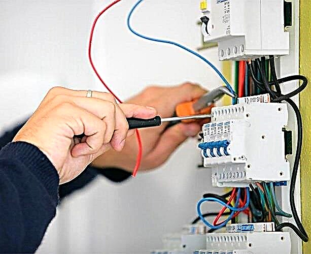
In electrical panels of private and apartment buildings, single-phase relays in a compact design on a DIN rail are usually used (+)
Three phase relay. Such RNAs are intended for industrial use. They are often used in protection schemes for three-phase machines. Moreover, if such a three-phase device is required at the input of such complex equipment, then it is often chosen in a combined version with control not only by voltage, but also by phase synchronization.
The main drawback and at the same time plus a three-phase relay is a complete power failure at the output when the voltage jumps even in one of the phase lines at the input. In industry, this is only beneficial. But in everyday life, voltage fluctuations in one phase are often not critical, and ILV takes and turns off the protected network.
In some cases, such a highly reliable reinsurance is needed. However, in the vast majority of situations, it is redundant.
By type of execution and dimensions
The entire range of voltage relays is divided into three types:
- adapter plug-socket;
- extension cords with 1-6 sockets;
- compact “bags” on a DIN rail.
The first two options are used to protect one specific electrical appliance or any group. They are plugged into a regular indoor outlet.
The third option is designed for installation in an electrical panel as part of a protective electrical system for an apartment or a cottage.
Image Gallery
Photo from
Regulator with extension cable
Three phase relay for heavy duty lines
Relays for installation in the electrical panel
Relay adapter for connection via a socket
Adapters and extension cords of the regulators in question are quite large. Manufacturers try to make them as small as possible so that they do not spoil the interior with their appearance.
But the internal components of the voltage relay have their own rigid dimensions, in addition, they still need to be combined in one housing with a socket and a plug. In terms of design, you will not expand here.
Relays on a DIN rail for installation in a distribution panel are more compact in size, there is nothing superfluous in them. Connecting them to the network is done by connecting wires and terminals.
According to the base and additional functions
The internal logic and operation of the relays for voltage control are built on the basis of a microprocessor or a simpler comparator. The first option is more expensive, but involves a more accurate and smooth adjustment of the ILV trip thresholds. Most of the protective devices sold are now built on a microprocessor base.

The upper (Umax) and lower (Umin) thresholds are the two main adjustable parameters of the ILV - if the input voltage is outside the set range, the relay disconnects the output line from the electric current (+)
At a minimum, a pair of LEDs are present on the relay housing, by which it is possible to determine the presence of voltage at the input and output. More advanced devices are equipped with displays showing the set permissible limits and the voltage available in the line.
The threshold values are adjusted by a potentiometer with a graduated scale or buttons with the display of parameters on the scoreboard.
The relay responsible for switching the relay inside the ILV is made according to a bistable circuit. This coil has two steady states. Energy is spent only on switching the latch. Electricity is not required to hold contacts in open or closed position.
On the one hand, this minimizes power consumption, and on the other, it ensures that the coil does not become warm during operation of the regulator.
When choosing a voltage relay in the parameters, you need to look at:
- operating range in Volts;
- the ability to set upper and lower thresholds;
- presence / absence of voltage level indicators;
- shutdown time when the ILV is triggered;
- delay time of renewal of supply of electricity;
- maximum switched power in kW or transmitted current in Amperes.
According to the last parameter, the relay should be taken with a margin of 20–25%. If there is no suitable ILV for the high load in the line, then a low-power model is taken, and a magnetic starter is connected at its output.
With setting thresholds, the situation is as follows. If they are set too hard, then the frequency of the relay will turn out to be high. Here you have to compromise.
The adjustment of these parameters must be carried out so that they provide the proper level of protection, but do not allow the ILV to switch too often. Constant on and off will not benefit both the equipment connected to the network and the voltage regulator itself.
However, some relays do not have the ability to independently adjust the thresholds. They have them installed “tightly”. For example, the factory set the lower limit at 170 V, and the upper limit at 265 V.
Such ILVs are cheaper, but they need to be selected more carefully. Then it will not work to reconfigure these devices, if there are errors in the calculations, you will have to purchase new ones to replace the unsuitable ones.

The choice of temporary parameters for disconnecting and restoring power to the output line depends on the connected load and the characteristics of a particular network (+)
If short-term (for fractions of a second) mild voltage drops constantly appear in the mains, then it is better to set the shutdown time to the lower threshold to the maximum. So there will be fewer trips, and the threat to powered equipment will be minimal.
The delay on inclusion should be selected depending on the type of electrical appliances included in the outlet. If the connected equipment has a compressor or an electric motor, then the voltage supply time should be increased to 1-2 minutes.
This will avoid sudden surges in voltage and current when power is restored in the network, which will protect refrigerators and air conditioners from breakdowns.
And for computers and TVs, this parameter can be reduced to 10–20 seconds.
Which is better: stabilizer vs relay
Often, instead of connecting a control relay in the shield, electricians recommend installing a voltage stabilizer in the house. In some cases, this is justified. However, there are a number of nuances that must be remembered when choosing one or another option, the protection of electrical appliances.
In terms of functionality, the stabilizer not only equalizes the voltage, but also turns off when the latter is too high. And the voltage relay is exclusively protective automation. It seems that the first includes the functions of the second.
But compared to the ILV stabilizer:
- more expensive and noisy;
- more inert with sudden changes;
- does not have the ability to adjust parameters;
- takes up much more space.
With a decrease in the input voltage, so that the necessary indicators are at the output of the stabilizer, it begins to “draw” more current from the network into itself. And this is a direct way to burnout wiring, if it was not originally designed for this.
The second main disadvantage of the stabilizer in comparison with the control relay is its inability to intercept a sharp surge in voltage when a zero break occurs.
Enough literally half a second with 350-380 watts in the socket, so that all the equipment in the house burned out. And most stabilizers are not able to adapt to such changes and misses the high voltage, disconnecting only 1-2 seconds after the start of the surge.
In addition to stabilizers and relays, it is also possible to use overvoltage and overvoltage releases to protect the line from voltage drops in the network. But in comparison with ILV, they have a longer response time. Plus, they do not turn on the power back in automatic mode, they are more like RCDs at work.
After a power outage, these releases will have to be manually reset.
ILV Connection Diagrams
In the shield, the voltage relay is always installed after the counter in the phase wire break. He must control and, if necessary, cut off precisely the "phase". You can’t connect it in any other way.

Most often, for single-phase consumers, the standard scheme with direct load through the relay (+) is used
There are two main schemes for connecting single-phase relays for a voltage regulator:
- with direct load through ILV;
- with load connection via contactor - with magnetic starter connection.
When installing an electrical panel in a house, the first option is almost always applied. A variety of ILV models with the necessary power on sale abound. Plus, if necessary, these relays can be installed in parallel and several, by connecting to each of them a separate group of electrical appliances.
With installation, everything is extremely simple. There are three terminals on the housing of a standard single-phase relay - “zero” plus phase “input” and “output”. It is only necessary not to confuse the connected wires.
To make it easier for you to navigate in the wiring diagrams and choosing the appropriate voltage regulator relay, we have made a selection of video materials describing all the nuances of this device.
How to protect equipment from fluctuations in the power supply using ILV:
Voltage Relay Setting:
Relays for monitoring the mains voltage are excellent protection against “zero breakage” and sudden changes in voltage. Connecting it is easy. It is only necessary to insert the corresponding wires into the terminals and tighten them.In almost all cases, the standard scheme with direct load through the ILV is used.
Share with your readers your experience in connecting and using voltage relays. Please leave comments, ask questions about the topic of the article and participate in discussions - the feedback form is located below.